Intel S1155 User Manual Page 14
- Page / 124
- Table of contents
- BOOKMARKS
- Legal Lines and Disclaime rs 2
- Contents 3
- Revision History 8
- 1 Introduction 9
- 1.1 References 10
- 1.2 Definition of Terms 10
- Introduction 12
- Specifications 13
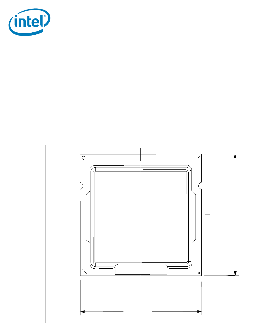
- 37.5 14
- 2.1.7 Processor Materials 16
- 2.1.8 Processor Markings 16
- Table 2-4. Storage Conditions 18
- 3 LGA1155 Socket 19
- 3.1 Board Layout 20
- 122.6 mil (3.1144mm) 21
- 36mil (0.9144 mm) 21
- 3.2 Attachment to Motherboard 22
- 3.3 Socket Components 23
- 3.5 Durability 25
- 3.6 Markings 25
- 3.8 Socket Size 26
- 4 Independent Loading 27
- Shoulder 30
- 6-32 thread 30
- Figure 4-4. ILM Assembly 31
- Load plate not 32
- 4.5 ILM Cover 33
- Step 3: Close ILM 34
- Step 1: PnP Cover installed 34
- Step 2: Remove PnP Cover 34
- 5 LGA1155 Socket and ILM 37
- 5.3 Loading Specifications 38
- 5.4 Electrical Requirements 38
- 6 Thermal Specifications 41
- 6.1.1 Intel 43
- 6.1.2 Intel 44
- Processor E3-1200 45
- 6.1.3 Intel 46
- 6.1.4 Intel 47
- 6.1.5 Intel 48
- Graphics Thermal Profile 48
- Thermal Sensor Exceeds T 49
- 6.1.7 Thermal Metrology 54
- 6.2.1 Processor Temperature 54
- 6.2.2.1 Frequency/VID Control 55
- 6.2.2.2 Clock Modulation 56
- 6.2.2.5 PROCHOT# Signal 57
- 6.3 Intel 58
- Turbo Boost Technology 58
- 6.4 Thermal Considerations 59
- 6.4.1 Intel 60
- Reporting 60
- System Thermal Response Time 61
- Turbo Algorithm Response Time 61
- Thermal Specifications 62
- 7 PECI Interface 63
- PECI Interface 64
- 8 Sensor Based Thermal 65
- 8.2.1 TTV Thermal Profile 67
- = (TTV T 69
- ) / Power 69
- 8.5 System Validation 73
- 9 1U Thermal Solution 75
- 1U Thermal Solution 76
- CASE_MAX 77
- 9.2.2 Thermal Solution 78
- 9.2.3 Assembly 79
- 9.3 1U Reference Heatsink 80
- 9.3.3 Assembly 81
- Die Centerline 82
- Package Centerline 82
- Active Tower Thermal Solution 83
- 10.3 Electrical Requirements 85
- 10.4 Cooling Requirements 87
- Thermal Solution Quality and 89
- Reliability Requirements 89
- A Component Suppliers 93
- B Mechanical Drawings 95
- TOP SIDE 98
- BOTTOM SIDE 98
- DETAIL A 99
- Mechanical Drawings 100
- C Socket Mechanical Drawings 115
- Socket Mechanical Drawings 116
- D Package Mechanical 121
- Drawings 121
- Package Mechanical Drawings 122
Related products and manuals for Processors Intel S1155
 (120 pages)
(116 pages)
(405 pages)
(52 pages)
(17 pages)
(636 pages)
(39 pages)
(24 pages)
(36 pages)
(56 pages)
(36 pages)
(70 pages)
(608 pages)
(504 pages)
(125 pages)
(116 pages)
(234 pages)
(172 pages)
(120 pages)
(116 pages)
(405 pages)
(52 pages)
(17 pages)
(636 pages)
(39 pages)
(24 pages)
(36 pages)
(56 pages)
(36 pages)
(70 pages)
(608 pages)
(504 pages)
(125 pages)
(116 pages)
(234 pages)
(172 pages)
© 2020, manymanuals.com. All rights reserved. | 2.410 s |
 Manymanuals.com
 Manymanuals.de
 Manymanuals.fr
 Manymanuals.it
 Manymanuals.pl
 Manymanuals.cz
 Manymanuals.es
 Manymanuals-pt.com
Comments to this Manuals